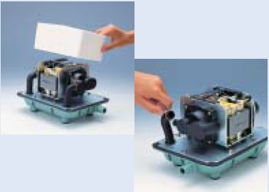

Step 1
REMOVAL OF THE CHAMBER BLOCKS
Remove the Upper Housing.

Step 2
Remove the sound absorber.
Pull out the L-tube from the casing nozzle.
Remove the four screws hold the chamber block and the casing block on both side. (4screws on each side)

Step 3
Remove one of the U-lock nuts hold the diaphragm mounting block to the rod.
• Use the box driver to loosen (or tighten) the U-lock nur.


Step 4
Remove one of the diaphragm mounting blocks from the actuating rod and pull out the other diaphragm mounting block with the rod and finally, separate the diaphragm mounting block and rod. This completes the chamber block removal procedure.
• When pull out the rod, take care not to allow the rod projection to accidentally hit the lever of the SP switch. If the pump stops automatically, the safety screw must be broken to prevent any further damage to the pump. Be sure all debris is removed from unit.

Step 5
FITTING THE CHAMBER BLOCKS
Install the new diaphragm mounting block on the actuating rod.
• Use new U-lock and washer only that come as replacement parts to prevent loosening and causing failure of the pump.

Step 6
Insert the actuating rod in accordance with the gap of the frame.
Secure the diaphragm mounting block on the other side and tighten the U-lock nut with the box driver
Make sure the gaps between the actuating rod and the electromagnet are even.

Step 7
Connect L-tube to the casing block and secure the casing with the screws. (4screws on each side)
Install the other casing block at the same way.

Step 8
REPLACEMENT OF SAFETY SCREW
Dispose of broken screw.
•Be sure all debris is removed from unit as it can result in damage to the permanent magnets and or even in a failure of the pump

Step 9
Draw a new safety screw through a hole in the different direction of the terminal. (Threading order : The L-shaped lever-the spring electrode)

Step 10
Fasten the screw with a nut.
The screw is designed so that the nut will turn freely when it is properly fastened, stop tightening when this happens.

Step 11
This completes the replacement of the safety screw procedure. Make sure the gaps between L-shaped lever and lug of the actuating rod are even.
• When checking the movement of the switch while the power is connected, touching the terminal will result in an electric shock.
• Unplug the pump immediately after the check.

Step 12
Install the sound absorber.

Step 13
Place the upper housing back on body.
• Be extremely careful not to pinch the Sound Absorber in the Upper Housing.
Secure it with the bolts. Then place the filter and filter cover on the upper housing.

